 , over the corrected image,
 , however, illustrates the difference remarkably:
The results of the Correct Intensity process for Data Sets 1, 2, and 3, all obtained from the same scanner, are evaluated in this section. The RF correction parameters use by the process igraph for all three data sets are listed in Table 8.9. Data Sets 4 and 5, obtained from a newer scanner, exhibit very little RF inhomogeneity and do not require correction.
Because the human eye is sensitive to ratios of intensities rather
than their absolute values [16], the difference between the
corrected and and uncorrected MR images is difficult to see. The ratio
of the uncorrected image,  , over the corrected image,
 , however, illustrates the difference remarkably:

In fact,  is exactly, the intensity variation due to
RF inhomogeneity as defined in Chapter 6 and should be
similar for both PD-weighted and T2-weighted volumes. Therefore,
 , calculated from the PD-weighted volume of each of the
data sets, will be presented for evaluation as well as selected image
slices before and after intensity correction. Directional brain
tissue intensity profiles and variances (see Chapter 2)
provide a quantitative evaluation of the Correct Intensity
process.
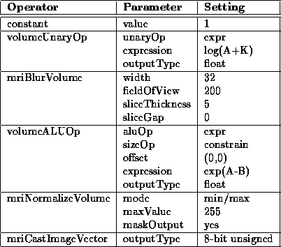
Table 8.9: Correct Intensity igraph
operator parameters for Data Sets 1, 2. and 3.
Figure 8.26 shows the RF inhomogeneity detected in Data Set 1 by the Correct Intensity process. Slice 16 of the PD-weighted volume, before and after intensity correction, is highlighted in Figure 8.27.
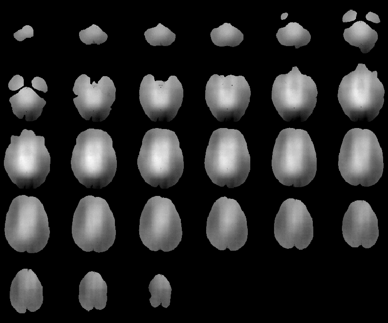
Figure 8.26: RF inhomogeneity detected in
MRI Data Set 1.
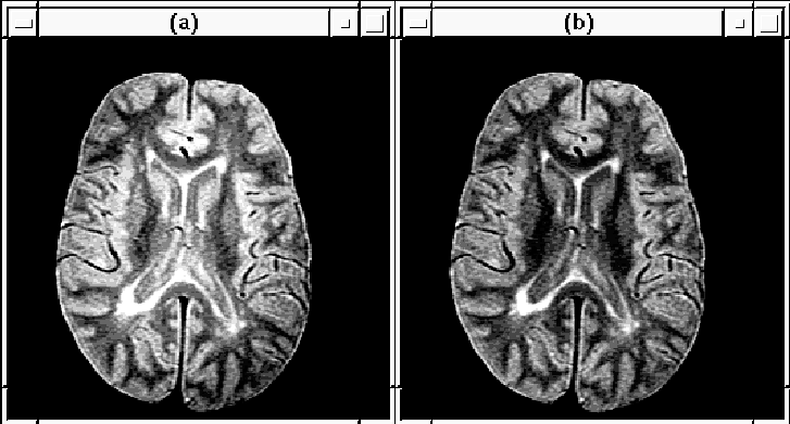
Figure 8.27: Slice 16 of MRI Data Set 1 (a) before
and (b) after RF correction.
The brain tissue intensity profiles in Figure 8.28 show that the intensity variation is reduced in the corrected MR volume. The change in tissue variance is shown in Table 8.10.
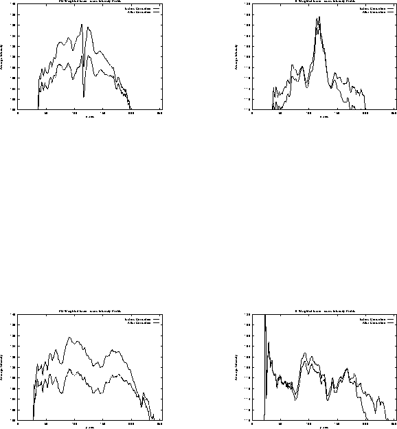
Figure 8.28: MRI Data Set 1 brain tissue
intensity profiles before and after RF correction.

Table 8.10: MRI Data Set 1 brain
tissue intensity variances before and after intensity correction.
The RF inhomogeneity detected in Data Set 2 by the Correct Intensity process is displayed in Figure 8.29. Slice 16 is highlighted in Figure 8.30.
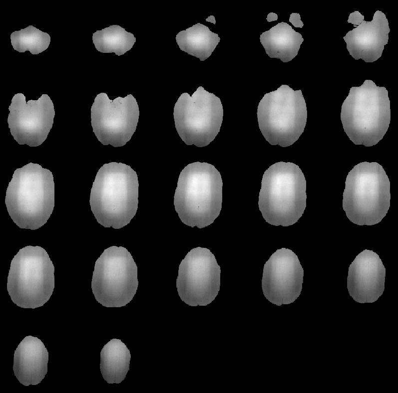
Figure 8.29: RF inhomogeneity detected in
MRI Data Set 2.
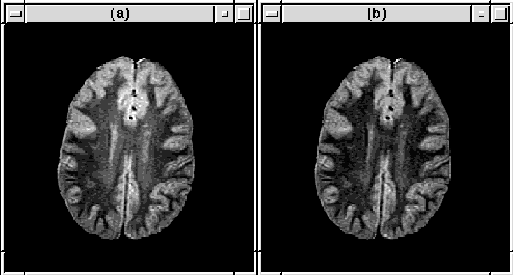
Figure 8.30: Slice 16 of MRI Data Set 2 (a) before
and (b) after RF correction.
The reduction in RF inhomogeneity in the corrected data set is obvious from the brain tissue intensity profiles shown in Figure 8.31 and the variances listed in Table 8.11.
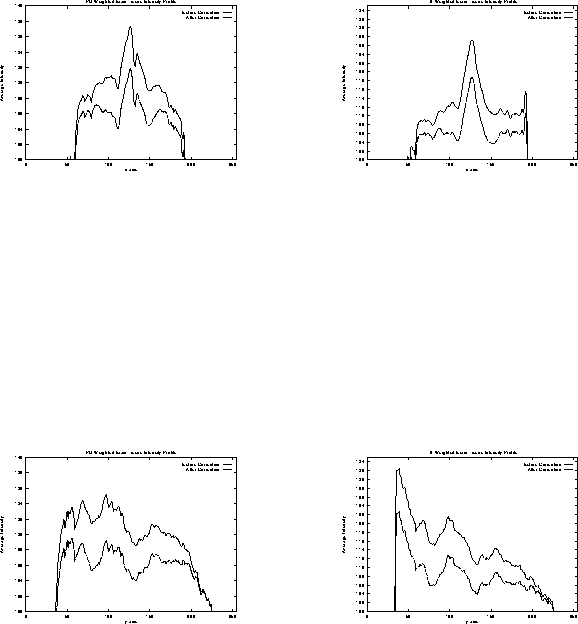
Figure 8.31: MRI Data Set 2 brain tissue
intensity profiles before and after RF correction.

Table 8.11: MRI Data Set 2 brain
tissue intensity variances before and after intensity correction.
The Correct Intensity process again reduces the intensity variation due to RF inhomogeneity in Data Set 3. The detected inhomogeneity is shown in Figure 8.32. Figure 8.33 obviates the correction to slice 16.
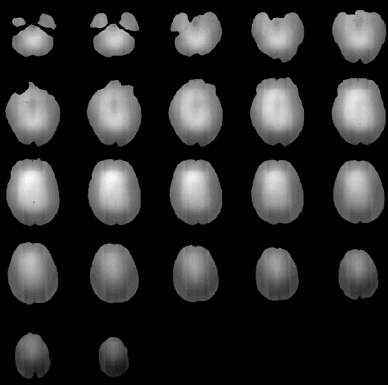
Figure 8.32: RF inhomogeneity detected in
MRI Data Set 3.
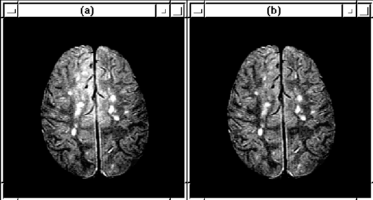
Figure 8.33: Slice 16 of MRI Data Set 3 (a) before
and (b) after RF correction.
Brain tissue intensity profiles, before and after intensity correction, are given in Figure 8.34. Changes in brain tissue variances are shown in Table 8.12.
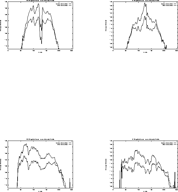
Figure 8.34: MRI Data Set 3 brain tissue
intensity profiles before and after RF correction.

Table 8.12: MRI Data Set 3 brain
tissue intensity variances before and after intensity correction.
Table 8.13 lists approximate benchmarks for the Correct Intensity igraph. The majority of the execution time can be attributed to the computation of the logarithm and the exponent functions. Because the data sets have maximum resolution of 12 bits, these functions could be optimized using lookup tables.
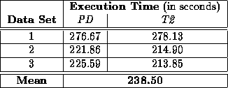
Table 8.13: Approximate benchmarks for the
Correct Intensity igraph running an a SUN SPARC 5 workstation.
Quantitatively, the Correct Intensity process reduces intensity variation due to RF inhomogeneity in Data Sets 1, 2, and 3. Such a reduction has been shown to improve the performance of algorithms used for automatic detection of MS lesions in MR images [26][54][24]. The impact that the corrected images presented herein have on Johnston's segmentation algorithm [21][23][22] is currently under investigation.