
 |
|
|
home |
personnel |
research |
facilities |
collaborations |
publications |
image database |
feedback
|
|
The Colour Problem Research Areas References |
Colour Constancy Algorithms
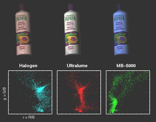
Figure 1 shows images of the same scene under three different illuminations. Below each image is a plot of the colours in chromaticity co-ordinates. The digital camera records large shifts in image colours under the different illuminations. However, a human observer viewing each scene will be able to discount the colour of the illumination and perceive the colours in each scene as the same. This property of compensating for illumination is called colour constancy.
Figure 1- Change in Image Colours with Illumination
Psychophysical experiments with human subjects have shown that although human colour constancy is quite good, it is far from perfect [BRAINARD92]. For the purposes of machine vision, a colour constancy method is one which extracts illumination independent colour descriptors from image data. The machine colour constancy problem can be defined as follows. First, chose some illumination as the standard, or canonical, illumination. The choice of canonical illumination matters little so long as it is not unusual. Then consider the 3 band RGB image obtained by any standard colour camera of a scene under some other, unknown illumination. The machine colour constancy problem requires converting the RGB at every pixel to be what it would have been had the same scene been illuminated by the canonical illumination. In this way, all the RGB values in the image of the scene measured under the unknown illumination are converted to a standardized RGB descriptors relative to the canonical illuminant. Once these standardized descriptors have been obtained, they can be used for object recognition or for creating an image of the scene as it would appear under some other illuminant. The key to solving this problem is discovering the colour of the unknown illumination. Two well known colour constancy methods which work under limited circumstances are the grey world algorithm and the white patch algorithm. The grey world algorithm assumes that the average of all colours in an image is grey, i.e. the red, green and blue components of the average colour are equal. The amount the image average departs from grey determines the illuminant RGB. The white patch algorithm, which is at the heart of many of the various retinex [LAND71] algorithms, presumes that in every image there will be some surface or surfaces such that there will be a point or points of maximal reflectance for each of the R, G, and B bands. The SFU Computational Vision Lab has developed two different approaches to machine colour constancy. One is based on a process of elimination that exploits the constraints that an image's RGB gamut places on possible values of the scene illumination. The second method learns the relationship between image RGBs and scene illumination using a neural network.
The gamut constraint method [FINLAY96, BARNARD95, FINLAY95] builds on initial work by Forsyth. [FORSY90] These variants will be collectively referred to as the gamut constraint method without trying to distinguish between the contributions of the various authors. The fundamental observation of the gamut constraint method is that not all possible RGB values will actually arise in images of real scenes. In advance, one might presuppose that the full range of positive values of R, G and B might be possible; however, if we take a database of hundreds of reflectance spectra from a wide variety of common objects and compute the RGB values that will arise if they are illuminated by the canonical illuminant, we find that the RGB values confine themselves to a subset of the theoretically possible values. The convex hull of this set of RGB values obtained under the canonical illuminant is called the canonical gamut. All RGB values inside the convex hull might arise because positive mixtures of the reflectance spectra in the database could be used to create new reflectances. Now consider an RGB triple a arising in an image of a scene under some unknown illumination. What does a’s presence reveal about the illumination? Since the canonical gamut represents the full set of RGB values ever expected to occur, a must have originated from the canonical gamut. However, since a has been obtained under an illuminant different from the canonical one it may no longer lie within the canonical gamut. The transformation required to map it back to the canonical gamut encodes information about the unknown illumination. Consider the following simple example in which the reflectance spectra
database has only four reflectances. The canonical gamut is defined by
the convex hull of the four database points, listed in Table 1 and plotted
in Figure 2.
Intensity has been eliminated by moving to two dimensional chromaticity co-ordinates. Figure 2 shows the chromaticities of the four surfaces defining the canonical gamut. Finlayson [FINLAY96] points out that this choice of chromaticity co-ordinates is crucial, since it preserves the diagonal model of illumination change that was present in the original 3 dimensional co-ordinates. In other words, to the extent that changes in illumination can be modelled by independent scaling of the R,G,B channels, then they can similarly be modelled by independent scaling of the resulting two chromaticity channels.
Figure 2 - Chromaticity Plot of Canonical Gamut
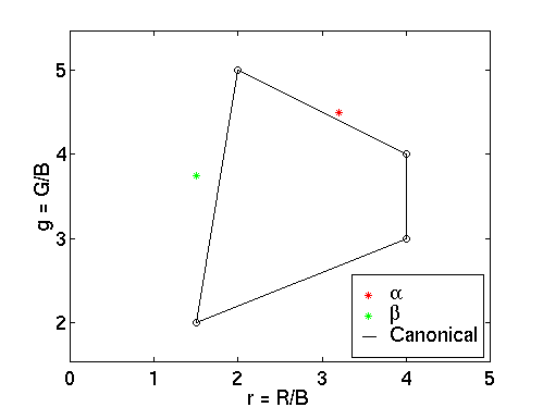
Consider an image RGB triple a=(19,27,6) converted to chromaticity co-ordinates a=(3.2,4.5), which turns out not to lie within the canonical gamut. What does it take to map it to the canonical gamut? If we suppose that a corresponds to one of the four known reflectances, say that represented by (1.5,2.0) in the canonical gamut, then to map it there requires a scaling of the first component by 0.47 and the second component by 0.44. On the other hand, it might correspond to the canonical gamut point (2.0,5.0) in which case a scaling of 0.63 and 1.1 is needed. The other two canonical gamut points yield two more scaling pairs. Figure 3 plots each of the possible mappings from a to hull vertices on the canonical gamut.
Figure 3 - Plot of Mappings of a to Canonical Gamut
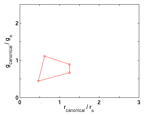
It might have been the case that a
corresponds to one of the points inside the convex hull of the canonical
gamut. However, only linear scaling is involved, so mapping to those interior
gamut points would only result in scaling within the interior of the convex
hull of the mappings in Figure 3. The convex hull of the set of mappings,
therefore, represents the complete set of mappings that could take a
into the canonical gamut.
The convex hull in Figure 3 shows the constraints that finding a in the image imposed on what the unknown illumination might be. The illumination must be represented by one of the points within the convex hull because these are all the illuminations that could possibly have resulted in one of the colours in the canonical gamut appearing as a. One RGB a yields constraints on the unknown illumination and a second RGB b will yield further constraints. Suppose b = (9,23,6), hence chromaticity (1.5,3.8), then the mappings taking b to the hull vertices of the canonical gamut are shown in Figure 4.
Figure 4 - Plot of Mappings of b to Canonical Gamut
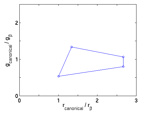
Since both a and b appear in the image, and by assumption, both scene points are lit by the same unknown illumination, the unknown illumination must be represented by one of the mappings in the intersection of the two convex hulls. All other candidate illuminations are eliminated from consideration. Figure 5 shows the intersection of possible mappings.
Figure 5 - Intersection of Constraints Imposed By a and b
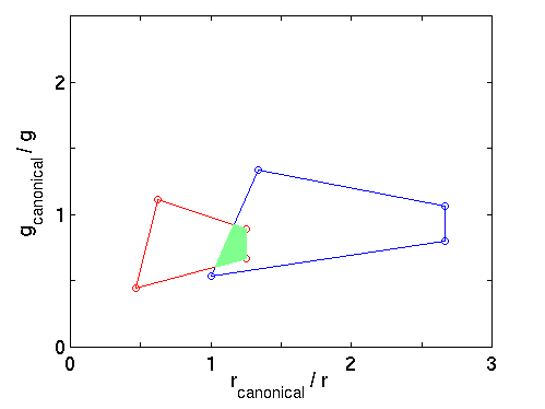
The convex hull of the set of distinct RGBs in the image is called the image gamut. Each vertex of the image gamut will yield some new constraints on the unknown illumination that can be intersected with the constraints obtained from the other vertices. Once the illumination constraint set has been established some heuristic method (e.g., the centre of the set) must be used to pick one of the remaining candidates as the estimate of the unknown illumination. The gamut constraint method can be extended by adding information about the set of possible illuminations to that about the set of possible surface reflectances. As with surface reflectance, measurement of many different light sources reveals quite a restricted gamut. The constraints implicit in the illumination gamut can then be intersected with the constraints from the image gamut to further eliminate illuminations as candidates for the unknown illumination.
Figure 6 - Varying Illumination

In many scenes there is not a single illumination, but rather the illumination varies gradually throughout the scene, as in Figure 6. This scene has quite a dramatic change in illumination from one part of the room to another. Barnard [BARNARD96] shows how to extract the information about the varying illumination field. Variation in illumination provides further constraints that can be incorporated into the gamut constraint method. Two image points which have been identified as being of the same surface, but under different illumination, yield constraints in an analogous fashion to those provided by two surfaces under a single illumination. The two situations are dual and their constraints can be combined to establish a more accurate estimate of the illumination throughout the scene than would be the case under spatially constant illumination. Interreflection between surfaces provides another common source of varying illumination. Since the interreflected light takes on some of the colour of the surface from which it is reflected, colour can be very useful in analysing interreflections [FUNT93]. Also when Interreflection is known to be the source of an illumination variation, then the colour shift can be exploited in establishing colour constancy [FUNT91].
Some of the SFU Computational Vision Lab's most recent work on colour constancy has been based on neural networks. Is it possible for a neural network to learn the relationship between an image of a scene and the chromaticity of scene illumination? If this relationship could be extracted by a neural network, then the trained network would be able to determine a scene's illumination from its image, which would then allow correction of the image colours to those relative to a standard illuminant, thereby providing colour constancy. Using a database of surface reflectances and illuminants, along with the spectral sensitivity functions of our camera, we generated thousands of images of randomly selected illuminants lighting ‘scenes’ of 1 to 60 randomly selected reflectances. During the learning phase the network is provided the image data along with the chromaticity of its illuminant. After training, the network very quickly outputs the chromaticity of the illumination given only the image data. We obtained surprisingly good estimates of the ambient illumination lighting from the network even when applied to scenes in our lab that were completely unrelated to the training data. Previous colour constancy algorithms generally employ assumptions either about the surface reflectances that will occur in a scene or about the possible spectral power distributions of scene illuminants. In contrast, the neural network approach involves no built-in constraints. It is an adaptive model that makes no explicit assumptions about the input data. All rules are implicitly learned from the training set. The experimental results show that the neural network outperforms the grey world and white patch algorithms, especially in the case of scenes containing a small number (1 to 5) of distinct RGB measurements, and performs comparably to the gamut constraint method. Good performance with only a small number of distinct RGB values means that the network is particularly well suited for processing small, local image regions. This is important because generally a scene contains more than one source of light, so the assumption that the scene illumination is constant will, at best, hold true only locally within an image. The neural network we used is a Perceptron [HERTZ91] with one hidden layer, as shown in Figure 7.
Figure 7 - Neural Network Architecture
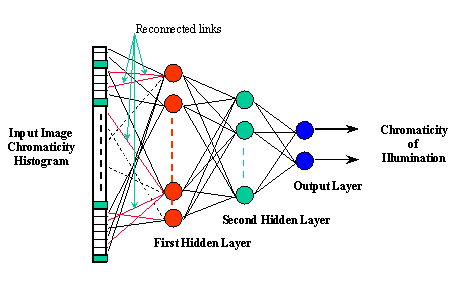
The neural network's input layer consists of 1000 to 2000 binary inputs representing the chromaticity of the RGB values present in the scene. The hidden layer has a much smaller size, usually about 16-32 neurons and the output layer is composed of only two neurons Each image RGB from a scene is transformed into an rg-chromaticity space. This space is coarsely, but uniformly, sampled so that all chromaticities within the same sampling square are treated as equivalent. Each sampling square maps to a distinct network input ‘neuron’. The input neuron is set either to 0 indicating that an RGB of chromaticity rg is not present in the scene, or 1 indicating that rg is present. Discretizing the image gamut in this way has the disadvantage that it forgoes some of the resolution in chromaticity due to the sampling; however, tests show that this is not too important. What is important is that it provides a permutation independent representation of the gamut which reduces the size of the input data set even though it is at the cost of a large input layer. The output layer of the neural network produces the values r and g (in the chromaticity space) of the illuminant. These values are reals ranging from 0 to 1. The network was trained using back propagation algorithm, without momentum [RUMEL] on a training set consisting of a large number of synthesized scenes, each with a random set of from 1 to 60 surface reflectances. The illuminant database contains the spectral power distributions of 89 different illuminants and the reflectance database contains the percent spectral reflectance functions obtained from 368 different surfaces. The training set was composed of 8900 ‘scenes’ (i.e. 100 scenes for each illuminant) and each scene had a random number of colours ranging from 1 to 60. Figures 8 and 9 show the result of colour correcting an input image
to the proper colour balance using the neural network.
The top left panel in Figure 9 is the input image supplied to the neural network under the unknown illumination. The top right panel shows the same scene captured under an illumination appropriate to the colour balance settings of the camera. This panel represents the "correct" colour balance. The lower left panel shows the input image colour corrected using the estimate of the illumination provided by the grey world algorithm. The lower right panel is the input image corrected using the neural network method.
Table 2 presents the comparison of several colour constancy methods tested
on a different sets of 100 randomly generated scenes, each with 10 distinct
surfaces.
To quantify error, the chromaticities of all the surfaces in the scene are corrected on the basis of each algorithm’s illumination estimate. This yields an image as the algorithm would expect it to be under the standard illuminant. The difference between the true chromaticities under the standard illuminant and those estimated by the algorithm is measured by the RMS error taken over all surfaces in the scene.
| |||||||||||||||||||||||||||||||
|
Computational Vision Lab Computing Science, Simon Fraser University, Burnaby, BC, Canada, V5A 1S6 | ||||||||||||||||||||||||||||||||
|
Fax: (778) 782-3045 Tel: (778) 782-4717 email: colour@cs.sfu.ca Office: ASB 10865, SFU |
| |||||||||||||||||||||||||||||||