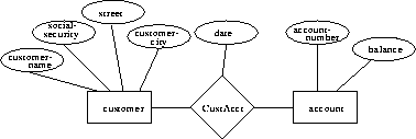
Figure 2.7: An E-R diagram


We can express the overall logical structure of a database graphically with an E-R diagram.
Its components are:

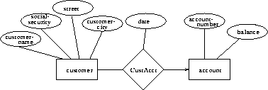
Figure 2.8: One-to-many from customer to account

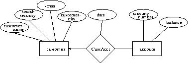
Figure 2.9: Many-to-one from customer to account

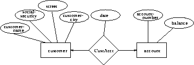
Figure 2.10: One-to-one from customer to account
Go back and review mapping cardinalities. They express the number of entities to which an entity can be associated via a relationship.
The arrow positioning is simple once you get it straight in your mind, so do some examples. Think of the arrow head as pointing to the entity that ``one'' refers to.