System Modeling
Based on Chp 5 of Sommerville “Software Engineering” (9th edition)
Introduction
system modeling is generally understood to be about creating graphical models of a system before implementing it in code
UML, the Unified Modeling Language, is a popular and standardized set of visual models for software
some popular types of UML diagrams
- activity diagrams
- use case diagrams
- sequence diagrams
- class diagrams
- state diagrams
Activity Diagram
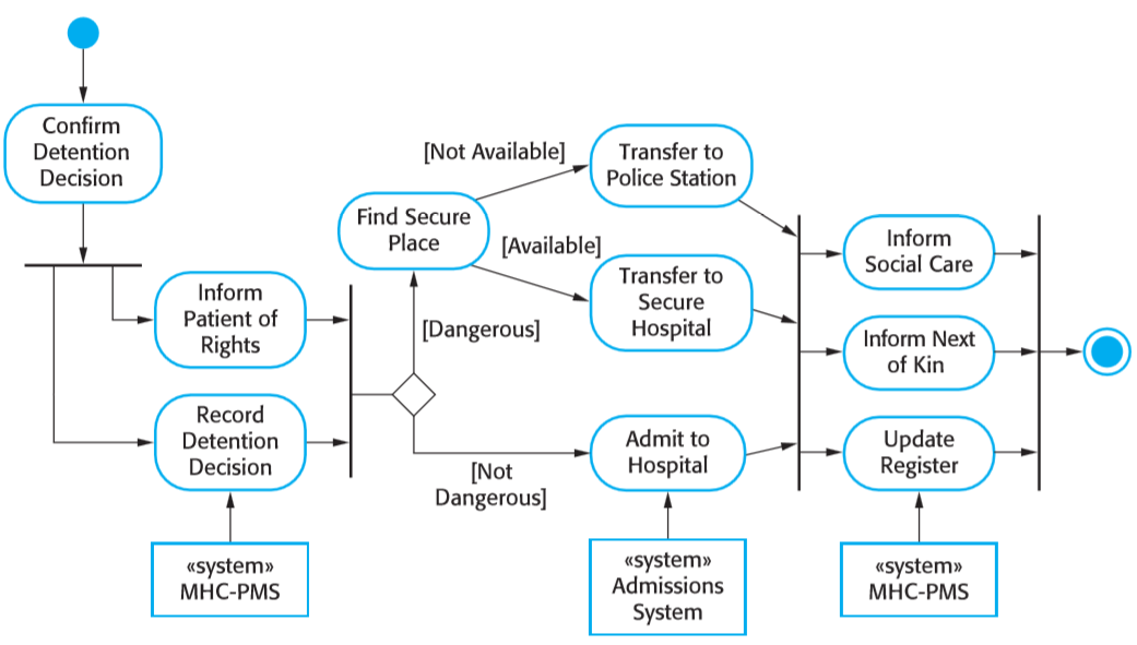
this diagram shows the process for how involuntary detention should be carried out for a patient suffering mental health problems that might be a danger to themselves or others
the filled-circle shows the begin and end of the activities
the arrows show the flow of activities
a long bar indicates that processes can be carried out in parallel (and all must be finished before going to the next step)
the value of such a diagram seems clear: it gives the precise steps of an important process in a compact way that is easy to understand
- imagine if this was written in plain English — it would be a long mess of if-statements
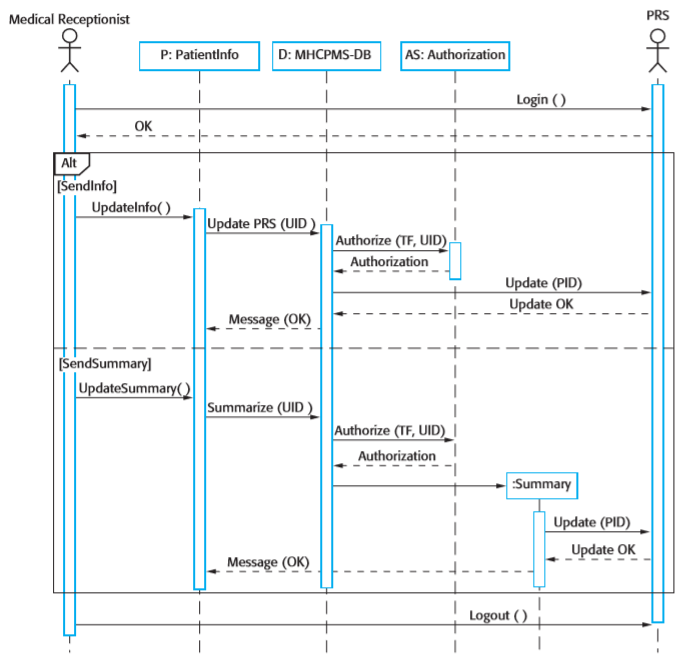
Sequence Diagrams
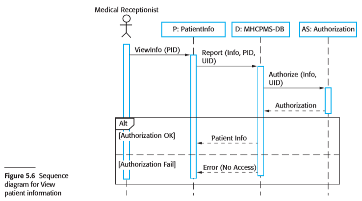
used to model interactions between objects
- e.g. human-database interaction, server-printer interaction, …
they diagram the interactions that take place during a single usage scenario
sequence diagrams are read from top to bottom
the “Alt” box shows a situation where alternative interactions are possible
Class Diagrams: Association
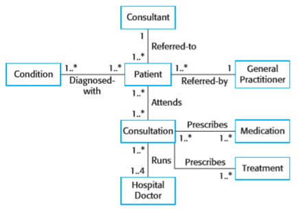
a class diagrams shows how the classes in an object-oriented system relate to each other
in this diagram, class are in rectangles, and the lines show how the objects of that class associate
e.g. if class A and class B are in a 1 .. 1 (one-to-one) relation, then each object of class A is associated with one object of type B, and vice-versa
if class A and class B are in a 1 .. * (one-to-many) relation, then each object of class A is associated with 0 or more objects of class B
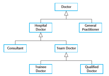
Class Diagrams: Inheritance
this class diagram shows an inheritance hierarchy
intuitively, the arrows in this diagram can be thought of as “is a” links, or inheritance links, or subclass links
an arrow from a class points to another class that generalizes it
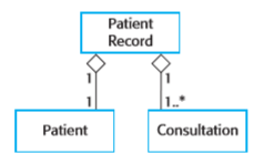
Class Diagrams: Aggregation
aggregation models objects that are composed of other objects
for example, a car object might consist of an engine object, some wheel objects, and some seat objects
the diamond shape at the end of a line indicates aggregation in UML
State Diagrams
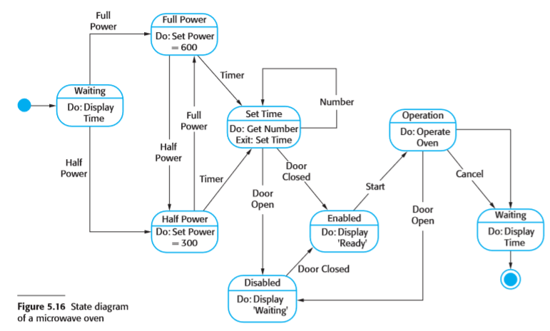
state diagrams are a graphical way of describing many simple machines
it turns out that many parts of real-world programs can be nicely described as state machines
for example, in the diagram below, the boxes represent states of the system, and the arrows indicate events that can occur that might change the state
State Diagrams
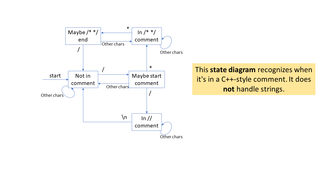
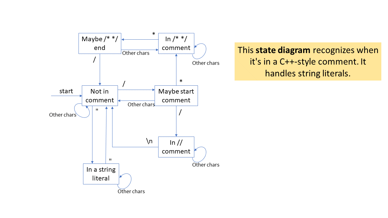
one general use of state diagrams is for problems related to parsing or tokenization
for example, suppose you want to write a program that will strip (remove) comments from a C++ program
C++ has both //-style comments and /* */-style comments
be careful: if // or /* or */ occurs inside a string, then they
shouldn’t be removed
imagine you are processing a C++ file, character by character
in this scenario, and event is reading a new character
this version handles strings
Designing vs Documenting
one final thought about system models
they can be used in at least two different ways:
- before/during design as a way to create the design
- after design as a way to document the design
UML-like diagrams do seem to be useful in many cases as ways of documenting designs
but they often seem less useful as a tool for actually creating designs
