17. Translating and Rotating
In these notes you will learn:
- How to apply translations to the Processing screen.
- How to apply rotations to the Processing screen.
- How to combine translations and rotations to make objects rotate around any point on the screen.
- How to use pushMatrix and popMatrix to transform more than one object at time.
These notes introduce two very useful geometric transformations: rotation and translation.
17.1. Coordinate Systems
Recall that Processing treats the screen as a rectangular array of pixels. By default, Processing labels each pixel in (column, row) form, starting at 0 in both the rows and columns. Thus, on the screen, the pixel in the upper-left corner is (0, 0), because it is in row 0 and column 0.
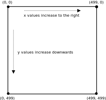
In other words, we can say that the default coordinate system for Processing puts the origin point (0, 0) in the upper-left corner of the screen, and the x-axis and y-axis are parallel to the sides of the screen.
As we will see, Processing lets you move the origin, and also rotate the entire coordinate system around the origin. By combining sequences of rotations and translations, you have complete control over the location and orientation of any object.
17.2. Translation
Translation is a geometric term that means “move”. When we translate a point, we move it to a new location by specifying how far it moves along the x and y axes.
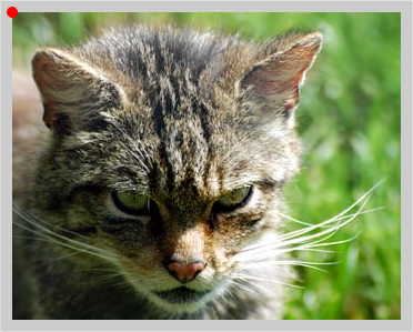
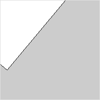
As mentioned, the default coordinate system for Processing puts the origin in the upper-left corner of the screen. For instance, in this picture of a cat, the origin is indicated by a red dot:
If we call translate(80, 100) before drawing the cat, then the origin moves 80 pixels to the right and 100 pixels down:
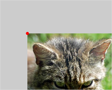
Since the origin of the coordinate system was moved before drawing the cat, when we do draw the cat it is drawn with respect to the newly placed origin. Thus it as if we moved the entire image down and to the right.
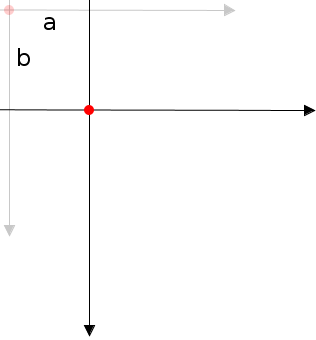
In general, calling translate(a, b) uses the current coordinate system to move the origin a pixels along the x-axis, and b pixels along the y-axis:
Here’s a new version of a program we’ve seen before:
void setup() {
  size(500, 500);
  smooth();
}

void draw() {
  background(255);

  translate(mouseX, mouseY);

  fill(255, 0, 0);
  noStroke();
  ellipse(0, 0, 75, 75);
}
This draws a circle centered at the mouse pointer. However, it does so by first moving the origin to the mouse pointer (using translate) and then drawing the circle at the origin.
This way of positioning items might seem strange at first, but it is actually quite common. It separates the positioning of an object from its shape.
17.3. Rotating the Coordinate System
Another useful transformation is rotation. Processing uses the rotate(rad) function to rotate the entire coordinate system around the origin. The parameter rad is how many radians to rotate clockwise.
Mathematically speaking, radians are the natural unit for measuring angles. However, it is often easier to think about rotations in degrees. We’ll mainly use degrees in these notes, and so we will write rotate(radians(deg)), where deg is the number of degrees we want the screen rotated. The expression radians(deg) converts degrees to radians.
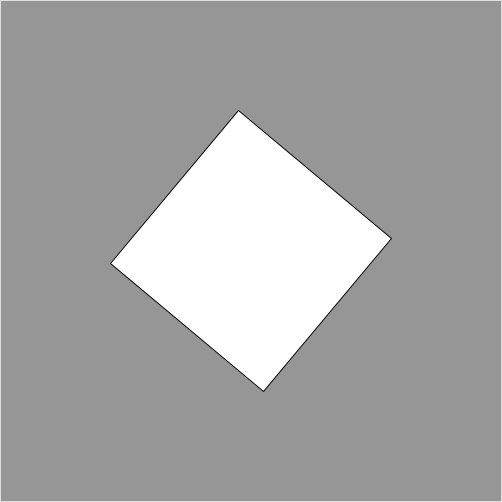
For example, this programs draws a square centered at the origin, and then rotates the entire coordinate system 40 degrees clockwise around the origin:
void setup() {
  size(500, 500);
}

void draw() {
  rectMode(CENTER);
  rotate(radians(40));
  rect(0, 0, 200, 200);
}
And here’s an animated rectangle:
float angle;

void setup() {
  size(500, 500);
  smooth();
  angle = 0;
}

void draw() {
  background(0);
  rectMode(CENTER);
  rotate(radians(angle));
  rect(0, 0, 200, 200);
  angle += 1;
}
You can control the speed and direction of the rotation by changing the statement angle += 1 to add (or subtract) a different value.
17.4. Combining Rotations and Translations
Rotations are nice, but there is a problem: how do you rotate an object around some point other than the origin? For instance, suppose we want a rectangle to rotate in the center of the screen at (250, 250).
One wrong approach is to draw the rectangle at (250, 250). Try writing rect(250, 250, 200, 200) in the previous program’s draw() function to see what happens. The problem is that rotate always rotates the entire coordinate system around the origin, no matter what is drawn on it. The result is the rectangle rotating around the upper-left corner, and not its middle point.
The correct way is to use translate to change the position of the origin before rotating. Thus, to rotate a rectangle in the middle of the screen around its center point we do the following steps:
- move the coordinate system origin to location (250, 250), i.e. the point we want to rotate around
- rotate the (entire) coordinate system around this new origin
- draw the rectangle centered at the origin (i.e. the upper-left pixel of the screen)
In code:
float angle;

void setup() {
  size(500, 500);
  smooth();
  angle = 0;
}

void draw() {
  background(150);
  rectMode(CENTER);

  translate(250, 250);
  rotate(radians(angle));

  rect(0, 0, 200, 200);
  angle += 1;
}
It’s important to understand that the order in which the statements are written matters: we first move the origin using translate, and then rotate the coordinate system with rotate. Something very different happens if you switch the order of these two statements:
rotate(radians(angle));
translate(250, 250);
Here we rotate the coordinate system first. Then, the origin is moved to (250, 250) in the rotated coordinate system. In other words, the origin is not moved to the pixel in row 250 and column 250 of the screen, but it is instead moved to (250, 250) of the rotated coordinate system. Try making this change in the sample program and you’ll see the difference.
17.5. Example: Benham’s Disk
Benham’s disk is an interesting toy that you may have seen in a science center. Basically, it’s a wheel, or top, that has this pattern on it:

Curiously, when you spin this disk quickly enough you will start to see colors even though the image is purely black and white.
Here’s an implementation of this in Processing:
PImage disk;
float angle;  // current angle of the disk
float dA;     // rate of disk's rotation

void setup() {
  size(500, 500);

  disk = loadImage("benhamsDisk.png");
  angle = 0;
  dA = 0;
}

void draw() {
  background(255);

  translate(250, 250); // move origin to center of screen
  rotate(angle);       // rotate angle radians around origin

  // draw the image so that its center is at the origin
  image(disk, -disk.width / 2, -disk.height / 2);

  angle += dA;

  // set the rate of rotation to be proportional to the y-value
  // of the mouse pointer
  dA = map(mouseY, 0, height, -1.0, 1.0);
}
In this program, the y-value of the mouse pointer controls the speed and direction of the disk. The map function is used to set the rate of rotation to be reasonable values between -1 and 1 radians per frame.
17.6. Rotating Two (or more) Things
The approach above works fine for rotating a single object, but what if we want, say, two squares, one centered at (125, 250) and the other at (375, 250), to rotate around their centers at the same time?
As a first attempt, lets just try doing it the “obvious” way and see what happens:
float angle1;
float angle2;

void setup() {
  size(500, 500);
  smooth();
  angle1 = 0;
  angle2 = 0;
}

void draw() {
  background(255);
  rectMode(CENTER);

  // red square
  translate(125, 250);
  rotate(radians(angle1));
  fill(255, 0, 0);
  rect(0, 0, 200, 200);
  angle1 += 1;

  // green square
  translate(375, 250);
  rotate(radians(angle2));
  fill(0, 255, 0);
  rect(0, 0, 200, 200);
  angle2 += -1;
}
The red square — the first one drawn — seems to rotate correctly around its center. But the green square orbits around the red one.
The problem is that when it comes time to do the translation and rotation for the green square, the translations and rotations for the red square are in effect, and so the coordinate system has already been altered. So, for example, the center of the green rectangle is not (375, 200) as we would like, but a continually changing point dependant on the angle of the red square.
What we really want to do is to apply the red square translations and rotations to the original un-rotated and un-translated coordinate system. One way to do this is to add an extra rotation and translation to undo the first two:
// square 1
translate(125, 250);
rotate(radians(angle1));
fill(255, 0, 0);
rect(0, 0, 200, 200);
angle1 += 1;

// undo the square 1 transformations
rotate(-radians(angle1));
translate(-125, -250);

// square 2
translate(375, 250);
rotate(radians(angle2));
fill(0, 255, 0);
rect(0, 0, 200, 200);
angle2 += -1;
This works, but there is an easier and more general way. It takes a bit of explaining, but once you get the hang of it you’ll be able to rotate anything in any way you want.
17.7. pushMatrix() and popMatrix()
To help you rotate more than one thing a time, Processing provides two helper functions: pushMatrix() and popMatrix(). These functions are used to save and restore the screen’s coordinate system.
Consider the following code (the code between calls to pushMatrix() and popMatrix() has been indented to make it stand out):
void draw() {
  background(0);
  rectMode(CENTER);

  // red square
  pushMatrix();
     translate(125, 250);
     rotate(radians(angle1));
     fill(255, 0, 0);
     rect(0, 0, 200, 200);
     angle1 += 1;
  popMatrix();

  // green square
  pushMatrix();
     translate(375, 250);
     rotate(radians(angle2));
     fill(0, 255, 0);
     rect(0, 0, 200, 200);
     angle2 -= 1;
  popMatrix();
}
When the pushMatrix() function is called the current coordinate system (i.e. translations and rotations) is saved in a special region of memory called the transformation stack. The coordinate system is also reset so that there are no rotations and the origin is in the upper-left corner.
When we are done drawing the red square, we call the popMatrix() function which restores the coordinate system to the state saved in the most recent call to pushMatrix(). It also deletes this coordinate system from the stack so that it can’t be “popped” again.
Together, these two functions let you save and restore different coordinate systems. This lets you use whatever coordinate system is most convenient for each part of your drawing.
17.8. Example: A Clock
Clocks are an intersting — and useful — example of animation. The following program draws the minute, second, and hour hand of a clock on the screen:
void setup() {
  size(500, 500);
}

void draw() {
  background(255);

  // get the current time
  int s = second();  // values from 0 - 59
  int m = minute();  // values from 0 - 59
  int h = hour();    // values from 0 - 23

  // move origin to center of the screen
  translate(250, 250);

  // draw the seconds hand
  pushMatrix();
  rotate(radians(map(s, 0, 59, 0, 360)));
  stroke(255, 0, 0);
  strokeWeight(1);
  line(0, 0, 0, -225);
  popMatrix();

  // draw the minutes hand
  pushMatrix();
  rotate(radians(map(m + s / 60.0, 0.0, 60.0, 0.0, 360.0)));
  stroke(0, 0, 255);
  strokeWeight(5);
  line(0, 0, 0, -200);
  popMatrix();

  // draw the hours hand
  pushMatrix();
  if (h > 12) h -= 12;
  rotate(radians(map(h + m / 60.0, 0.0, 24, 0.0, 360.0)));
  strokeWeight(5);
  stroke(0, 255, 0);
  line(0, 0, 0, -100);
  popMatrix();

  // "button" at the center
  fill(0);
  noStroke();
  ellipse(0, 0, 15, 15);
}
Note the following:
The functions second(), minute(), and hour() are built into Processing and return the current seconds, minutes, and hour of the current time according to your computer. Your computer’s time is probably set to the actual time, and so, when run, this program should show the current time.
pushMatrix and popMatrix must be used when drawing each hand. That’s because the three hands each have their own particular angle independent of the others. The pushMatrix() function saves the current coordinate system, while popMatrix() restores the coordinate system to the way it was just before the most recent call to pushMatrix. The idea is that before we draw the hand of a clock we save the coordinate system so that we can later reset the coordinate system before drawing the other hands.
Try commenting-out pushMatrix and popMatrix to see what happens.
Take a look at the rotate command used for drawing the seconds hand:
rotate(radians(map(s, 0, 59, 0, 360)));
We know the variable s is between 0 and 59 because that is how the seconds() works. We want the angle of the second to range from 0 to 360 degrees because it goes all the way around the (circular) clock. Thus, we use map modify the value of s to be at the proportionally same location in the range 0 to 360.
The rotate command for drawing the minutes hand (and the hours hand) is a little more complex:
rotate(radians(map(m + s / 60.0, 0.0, 60.0, 0.0, 360.0)));
Instead of mapping m along, we map m + s / 60.0. The reason for this is that it enables the minutes hand to be drawn part-way between two different times. Thus it appears to slide smoothly around the clock. This is in contrast to the seconds hand which clearly jumps from second to second.
In this example we’ve drawn the hands of the clocks as lines to mimic an ordinary wall clock. However, you can draw pretty much whatever your like instead of lines, and so it is possible to create all kinds of interesting clocks. It’s quite challenging to create a clock that is both visually interesting and easy to read!
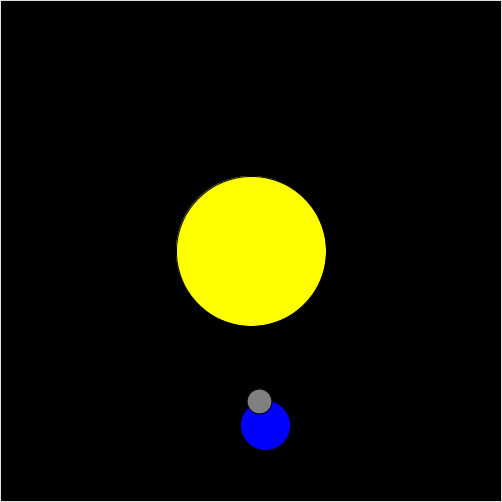
17.9. Example: The Sun, The Earth, and The Moon
As an example of how to use pushMatrix and popMatrix, lets create an animation of the sun (a big yellow circle), the earth (a medium blue circle going around the sun), and earth’s moon (a small gray circle going around the earth).
Indentation has been added to help show what code is between each call to pushMatrix and popMatrix.
float angleEarth;
float angleMoon;

color YELLOW = color(255, 255, 0);
color BLUE = color(0, 0, 255);

void setup() {
  size(500, 500);
  angleEarth = 0;
  angleMoon = 0;
  smooth();
}

void draw() {
  background(0);   // comment out this line to get a nice trail effect

  // draw the sun
  pushMatrix();
     translate(250, 250);   // center of the sun is origin
     fill(YELLOW);
     ellipse(0, 0, 150, 150);
  popMatrix();

  // draw the earth rotating around the sun
  pushMatrix();
     translate(250, 250); // center of the sun is origin
     rotate(angleEarth);
     translate(175, 0);   // center of the earth is origin
     fill(BLUE);
     ellipse(0, 0, 50, 50);
     angleEarth += 0.01;

     // draw the moon rotating around the earth
     pushMatrix();
        rotate(angleMoon);  // origin is currently at the Earth's center
        translate(25, 0);
        fill(128);
        ellipse(0, 0, 25, 25);
        angleMoon += 0.04;
     popMatrix();

  popMatrix();
}
This is program really tests your understanding of pushMatrix() and popMatrix(). Indeed, the first time I wrote a program like this I didn’t completely understand those functions, and so it took a lot of trial and error to end up with a program that worked (and which I didn’t understand).
When we start using object-oriented programming, it turns out we can usually hide the details of pushMatrix() and popMatrix(). This greatly simplifies our programs.
17.10. Questions
- By default, where on the screen is the origin of the Processing coordinate system?
- What does the statement translate(5, 10) do? Be precise.
- What are radians?
- What does the statement rotate(radians(45)) do? Be precise.
- Briefly describe what pushMatrix() and popMatrix() do.
17.11. Programming Questions
A snowman consists of three circles stacked on top of each other. Draw a snowman that follows the mouse pointer. Use translate to do all the movement. Important: your ellipse statements should only contain numbers as parameters.
Write a program that draws a triangle, one of whose corners is at (0, 0). Make the triangle continuously rotate around (0, 0).
Write a program that draws a windmill blade that looks something like this:
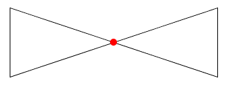
The blade should rotate around the center (the red dot), and the entire blade should be on the screen at all times.
Modify the Benham’s disk program from the notes so that the value of dA is printed near the upper-left corner of the screen.
Write a program that displays a PImage in the center of the screen and then rotates counter-clockwise as the mouse moves to the left, and clockwise as it moves to the right.
Modify the clock program in the notes so that the second hand slides smoothly around the clock instead of jumping from second to second.
Add another planet, with its own moon, to the solar system program from the notes. Make its speed and size different than the planet/moon already there.