Assignment 1 - Model Rendering
Due Date: 6
October 2003
General description
For this assignment, you are required to write a program to interpret input scene files (see the section Simple Scene Description Language below), and display the scenes thus described using OpenGL library. The program that you submit must use no external routines other than the standard C/C++ libraries (iostream, math, ...) and OpenGL libraries (gl, glut, ...).
Testing and output
Your program should take a single argument that is a filename. This filename specifies the file that the program displays. for example:
./mrender scene.pov (linux)
We will provide a few test files (with descriptions of the proper output) that you should run your program on. However, we will mark your assignment using a different set of test files, so be sure that your program works for any valid scene file!
Sample files (note that pov files are in text format):
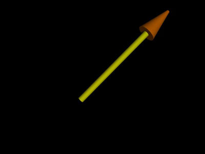
sample-1-1.pov (output)
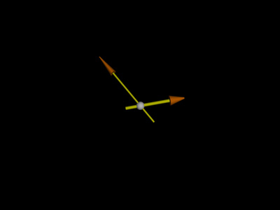
sample-1-2.pov (output)
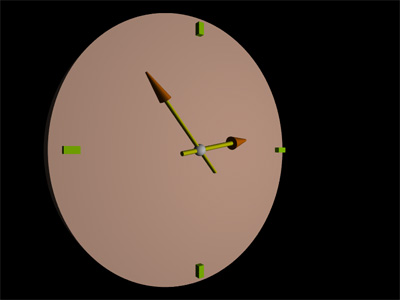
sample-1-3.pov (output)
You are also required to design one scene containing 3-D block letters lined up to spell your last name (lucky if you have a short one!!!)
Simple Scene Description Language
The simple scene description language (SSDL) is a simplified version of the
POV-RayTM
Scene Description
Language. So, you may use Pov-RayTM to test
correctness of output of your program. POV-RayTM
(Persistence of VisionTM Raytracer) is one of
the most popular tools for producing high-quality computer graphics. POV-RayTM
is copyrighted freeware so it can be used for no charge, subject to the
conditions stated in the authors'
license. POV-RayTM is installed and works
fine on the CSIL linux machines. Example of usage:
povray test.pov +W800 +H600
We describe the coordinates using a three-part vector. A vector is specified by putting three numeric values (float or integer) between a pair of angle brackets and separating the values with commas: <X, Y, Z>
Pov-RayTM uses the left-handed coordinate system, i.e. it has the positive y-axis pointing up, the positive x-axis pointing to the right, and the positive z-axis pointing into the screen. You should consider this in your program to get the same output for same scene files.
White space includes the blank (space character), tab, end-of-line, form feed, and comments. The comments for the scene description language are C-style single line comments (//). Any characters appearing after it on a line of input should be ignored.
In POV-RayTM Scene Description Language, there are #include statements which are used to include other files (e.g. definition of shapes, ...). By now, for compatibility reasons, we will ignore #include statements in our SSDL files (treat them as comments).
Numbers are C-style float numbers (e.g. 2.75, 2, .5). Statements are case sensitive.
Your parser is required to operate correctly on syntactically-correct input. On syntactically-incorrect input, any behavior is acceptable. You can either terminate the program with an error message, or continue running the program if the error can be ignored (e.g. <X Y Z> instead of <X, Y, Z>).
The following commands are present in the SSDL:
camera
{
location <Xl, Yl, Zl>
look_at <Xa, Ya, Za>
right <Xr, Yr, Zr>
// horizontal size of view
up <Xu, Yu, Zu>
// vertical size of view
[Transformations]
// See section for transformations
}
The camera statement describes where and how the camera sees the scene.
It gives x-, y- and z-coordinates to indicate the position of the camera and
what part of the scene it is pointing at. Note that the projection is a
perspective projection.
light_source {
<X, Y, Z>
// light's position
color rgb <R, G, B>
// light's color, range: 0-1
[Transformations]
}
Creates a regular point light source (an invisible tiny point that emits
light).
Basic Shapes
box
{
<X1, Y1, Z1> // near lower left corner
<X2, Y2, Z2> // far upper right corner
pigment {color
rgb <R, G, B>}
[Transformations]
}
Creates a box that extends between the opposite corners. The first vector
is generally the minimum x-, y- and z-coordinates and the 2nd vector should be
the maximum x-, y- and z-values however any two opposite corners may be used.
Box objects can only be defined parallel to the axes of the world coordinate
system. We can later rotate them to any angle using transformations.
The pigment statement defines the surface color of the object.
sphere
{
<X, Y, Z> //
center of sphere
R
// radius of sphere
pigment {color
rgb <R, G, B>}
[Transformations]
}
Creates a sphere shape.
triangle
{
<X1, Y1, Z1>, // <Vertex1>
<X2, Y2, Z2>, // <Vertex2>
<X3, Y3, Z3> // <Vertex3>
pigment {color
rgb <R, G, B>}
[Transformations]
}
cylinder
{
<X1, Y1, Z1>, // coord of one end
of cylinder
<X2, Y2, Z2>, // coord of other
end
R
// size of cylinder
pigment {color
rgb <R, G, B>}
[Transformations]
}
Creates a capped cylinder between two specified points.
cone {
<X1, Y1, Z1>, R1, //
coordinates and radius of one end of cone
<X2, Y2, Z2>, R2
// coordinates and radius of other end
pigment {color
rgb <R, G, B>}
[Transformations]
}
Creates a clipped capped conical shape between two specified points.
union {
OBJECTS // basic shapes or other
union statements
[Transformations]
}
Bind two or more shapes into a single entity that can be manipulated as a
single object.
translate <Tx,
Ty, Tz>
Moves the element relative to it's current position
scale <Sx,
Sy, Sz>
Changes the size of the object according to the scale factors
rotate
<Dx, Dy, Dz>
Rotates the object around the x-, y- and z-axis. The rotation parameters
are in degrees.
matrix
<m11, m21, m31,
m12, m22, m32,
m13, m23, m33,
m14, m24, m34>
Specifies the transformation matrix to be used by objects. The matrix is
the transpose matrix of a standard 3D transformation matrix, after ignoring the
forth column that is always <0, 0, 0, 1>. So, x2 =
m11*x1 + m12*y1+m13*z1+m14, etc.
Design, Coding & Documentation
The first thing that you should do (after reading the whole assignment) is to design the objects. This is a critical task. Do not delay this task, do not fudge it, do not proceed to code without most of this design finished. You will be constructing a fair amount of software and having to change object specs as you are coding will just mean a lot of extra work (which you don't have time for, trust me). For each object you design, write down a brief description of its duties and members (data and functions). If unsure, discuss your design with me or the T.A.
To get started with the design, consider the following. Do not limit yourself to the ideas presented here; these are just to get you thinking:
You should probably have a class for each type of the objects (camera, light, shapes, transformations). Objects can be either one or a group of the basic shapes, each with different attributes.
How should you store the transformations? Should you store a list of transformations related to each object as an attribute of that object?
You should probabely have a Parser class that can read the input file (which is a bunch of characters) and returns tokens (e.g. NUMBER, CAMERA, PIGMENT, ....)
Should you have a member function for each object that calls the parser member functions according to the parameters that object needs?
The marks given for design on this assignment (and all assignments) are for embodied design---that is, design that has made its way into code. A supplementary document or comments explaining what you would do in code will not receive design marks.
You should use Linux for developing your program. You can use KDevelop IDE (is already installed on CSIL linux machines) or your own favorite IDE/text editor. The important thing is that in your submission, you should also hand in a Makefile (KDevelop generates this Makefile automatically) so that your program can be compiled using a single make command in CSIL linux machines. If you are not a hardcore fan of programming in Linux, don't panic; try to attend the tutorials and office hours and always keep that positive ness in your mind that what you are doing now is important for your future career.
Remarks:
Your main reference for the questions regarding the effect of the commands (e.g. transformations) on the scene, is POV-RayTM. You can run it with your input scene file to see how the commands are describing the scene. Although the output of your own program will not be as high-quality as the output of a ray-tracer, they should look more or less similar in structure.
If there are variables that neither have a default value nor are specified in the SSDL file, define them as an attribute and initialize them with a default value in the constructor. Do not use constants, not only for the sake of design, but also because you may have to change them all in the next assignments.
Marking
| 20% | Program design and coding style |
| 20% | File handling and parser |
| 50% | Correctness (shapes, transformations, ...) on the unknown test suit |
| 10% | Scene file for your name |
Last updated in Sept 27, 2003