17. Translating and Rotating
In these notes you will learn:
- How to apply translations to the Processing screen.
- How to apply rotations to the Processing screen.
- How to combine translations and rotations to make objects rotate around any point on the screen.
- How to use pushMatrix and popMatrix to transform more than one object at a time.
These notes introduce two very useful geometric transformations: rotation and translations.
17.1. Coordinate Systems
Recall that Processing treats the screen as a rectangular array of pixels. By default, Processing labels each pixel in (column, row) form, starting at 0 in both the rows and columns. Thus on the screen, the pixel in the upper-left corner is (0, 0), because it is in row 0 and column 0.
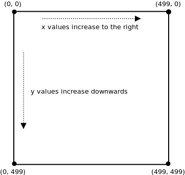
In other words, we can say that the default coordinate system for Processing puts the origin point (0, 0) in the upper-left corner of the screen, and the x-axis and y-axis are parallel to the sides of the screen.
As we will see, Processing lets you move the origin around, and also rotate the entire coordinate system around the origin. The former is known as a translation and the latter as a rotation. By combining sequences of rotations and translations, you have complete control over the location and orientation of any object.
17.2. Translations
Translation is a geometric term that means “move”. We “Translate” each of the objects points from (x, y) to some (x + c1, y + c2), where c1 and c2 are constants. That is, any point that we specify is drawn with those constants added on.
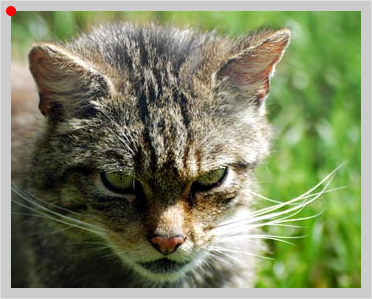
In the following example, consider first the position of the origin, indicated by the red dot and suppose the image of the cat is drawn using the call image(cat, 0, 0).
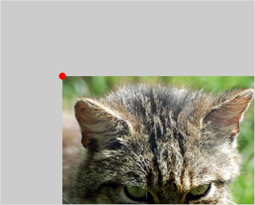
Now suppose we call translate(80, 100) before drawing the cat. The result of this is that if we were to draw anything, say a rectangle, at some position (x, y), after the call to translate, the shape will actually be drawn at position (x + 80, y + 100). So in our example, the picture of the cat is drawn at image(cat, 0 + 80, 0 + 100):
Here’s a variation on the first program we wrote:
void setup() {
    size(500, 500);
    smooth();
}

void draw() {
    background(255);

    translate(mouseX, mouseY);

    fill(255, 0, 0);
    noStroke();
    ellipse(0, 0, 75, 75);
}
Like the original, this program draws a circle centred at the mouse pointer. The difference is that this time the program first changes the origin of the screen to the position of the mouse (using translate) then draws the circle at the origin.
This method of positioning items might seem odd at first, but it is actually very prevalent. The advantage in doing this is that it allows us to separate the position of an object from its shape.
17.3. Rotating the Coordinate System
Another useful transformation is the rotation. Processing uses the rotate(rad) function to rotate the entire coordinate system around the origin. The parameter rad specifies how many radians to rotate. A positive rad value rotates clockwise while a negative rad values rotates counter-clockwise. As a reference, here are some common clockwise rotations in degrees and radians.
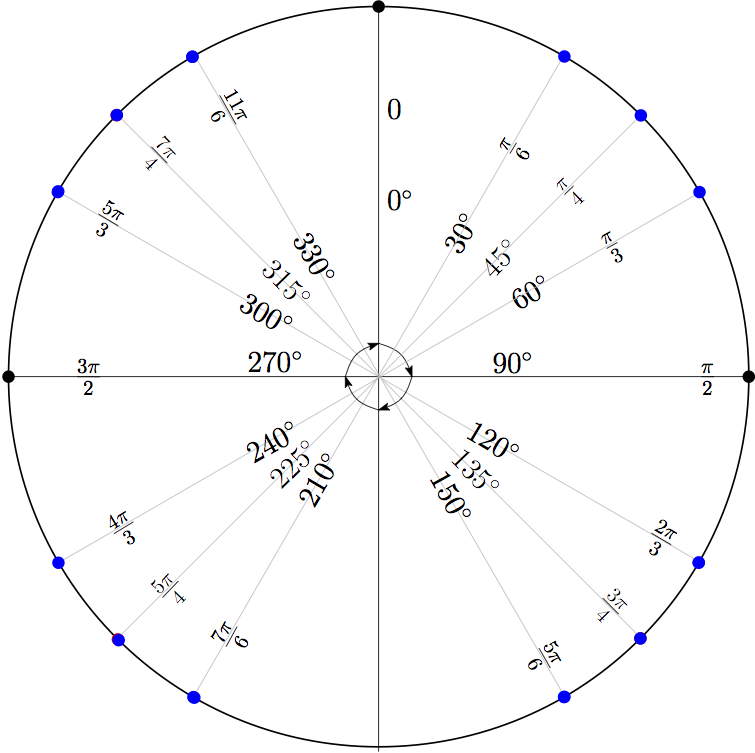
Mathematically speaking, radians are a more natural unit for measuring angles than degrees are, since an angle’s measurement in radians is equal to the length of a corresponding arc of a unit circle. However it often easier to think about rotations in degrees. Since the rotate function takes radians, we must convert the degree value first using the radians() function, which takes a float deg and converts it radians.
For example consider the following program, which first rotates the coordinate system by 40 degrees and then draws a rectangle centred at the origin.
void setup() {
    size(500, 500);
    rectMode(CENTER);
}

void draw() {
    rotate(radians(40));
    rect(0, 0, 200, 200);
}
Note that the rotation of the coordinate system resets on every call to draw(). That is, the call to rotate produces a rotation of 40 degrees from 0, rather than a cumulative rotation. On the other hand, calling rotate() multiple times inside draw will result in a cumulative change: calling rotate(deg1) immediately followed by calling rotate(deg2) is equivalent to calling rotate(deg1 + deg2).
Let’s animate the rectangle:
float angle;

void setup() {
    size(500, 500);
    smooth();
    angle = 0;
    rectMode(CENTER);
}

void draw() {
    background(0);
    rotate(radians(angle));
    rect(0, 0, 200, 200);
    angle += 1;
}
17.4. Combining Rotations and Translations
Rotations are nice, but there is a problem: how do you rotate an object around some point other than the origin? For instance, suppose we want a rectangle to rotate in the centre of the screen, at (width/2, height/2).
One wrong approach is to draw the rectangle at (250, 250). If we try changing the rect statement of the previous program to rect(250, 250, 200, 200) we won’t get what we want. The problem is that rotate always rotates the entire coordinate system around the origin, no matter what is drawn on it. The result is the rectangle rotating around the upper-left corner, and not its middle point.
The correct way is to use translate first to change the position of the origin before rotating. This to rotate a rectangle in the middle of the screen around the screen’s centre point we follow the following steps:
- move the coordinate system origin to location (width / 2, height / 2) using translate().
- rotate the (entire) coordinate system around this new origin
- draw the rectangle centred at the origin
In code:
float angle;

void setup() {
    size(500, 500);
    smooth();
    angle = 0;
    rectMode(CENTER);
}

void draw() {
    background(0);
    translate(width / 2, height / 2);
    rotate(radians(angle));
    rect(0, 0, 200, 200);
    angle += 1;
}
It’s important to emphasize that the order in which the statements are written matters: we first move the origin using translate, and then rotate the coordinate system using rotate. Were you to replace the order of the two statements, writing instead:
rotate(radians(angle));
translate(width / 2, height / 2);
You get a wildly different result. Here we rotate the coordinate system first. Then the origin is moved to (width / 2, height / 2) in the rotated coordinate system. In other words the origin is not moved to the pixel in row width / 2 and column height / 2 of the screen, but is instead moved to point (width / 2, height / 2). The result is the same as if we were to call rect(250, 250, 200, 200), with out translating first (why?).
17.5. Example: Drawing Angles on a Circle
To illustrate rotations consider the following example which draws angles on the circle in 15 degree increments:
color red = color(255,0 ,0);
color green = color(0, 255, 0);
color blue = color(0, 0, 255);

float diam;
float angle;
float dAngle;

int drawRate;

void setup() {
    size(500, 500);
    background(255);
    smooth();
    angle = 0;
    drawRate = 15;
    dAngle = 15;
    diam = 480;
}

void draw() {
    noFill();
    stroke(0);
    strokeWeight(1);
    ellipse(250, 250, diam, diam);
    translate(250, 250);
    strokeWeight(3);
    if (frameCount % drawRate == 0) {

        if (angle % 90 == 0) {
            stroke(0);
        } else if (angle % 30 == 0) {
            stroke(blue);
        } else if (angle % 45 == 0) {
            stroke(red);
        } else {
            stroke(green);
        }

        rotate(radians(angle));
        line(0, 0, 0, -diam / 2);
        if (angle < 360) {
            angle += dAngle;
        } else {
            noLoop();
        }
    }
}

void keyPressed() {
    if (key != CODED) {
        if (key == ENTER || key == RETURN) {
            background(255);
            setup();
            loop();
        }
    }
}
We draw the background once in setup(), rather than redrawing at every call to draw(). This allows us to reuse some of the code since we need not redraw all of the lines.
Having setup the program, the first thing we must do is translate the origin to the centre of the screen. To make the angles clearer, we’ll colour them based on which different angles. This is what the if-else-if statement does. Having set the colour, we rotate the coordinate system by angle degrees.
Note that we draw the line always starting at the origin, and extending to the point (0, -diam / 2). This is a line segment of length diam / 2. Because of the translation it starts at the centre of the circle, and thanks to the rotation, it’s end point is rotated 15 degrees clockwise at each call to draw().
Further note that we only draw the line and update the angle when the drawRate we’ve decided on divides neatly into the number of times draw() has been called. Try changing the value of drawRate to see what happens.
Having drawn the line, we check that the angle is less than 360 degrees since there’s no point in continuing to draw if we’ve gone around the circle once. If it is, then since the rotation is reset with each call to draw(), we add 15 to angle, making the next rotation angle + 15.
Further note, that once we have gone around the circle once, the else block of the code is executed and the special noLoop() function is called. What this function does is tell processing to stop calling draw(). We can use the noLoop() function, and it’s counterpart loop(), to easily restart the animation should the user choose to. We’ll implement it so that whenever the ENTER button is pressed, the animation starts over.
void keyPressed() {
    if (key != CODED) {
        if (key == ENTER || key == RETURN) {
            setup();
            loop();
        }
    }
}
When a ENTER key is pressed, the setup() function is called once, followed by draw() repeatedly, since loop() tells processing to start calling draw() again. We have effectively restarted our program. This is one of the many advantages of keeping your code organized into named blocks — reusability.
17.6. Example: Benham’s Disk
Benham’s disk is an interesting toy that you may have seen in a science centre. Basically, it’s a wheel that has this pattern on it:

Curiously, if you spin this disk quickly enough and start at it a little, you will start to see colours even though the image is purely black and white.
Here’s an implementation of this using Processing
PImage disk;
float angle;
float dA;

void setup() {
    size(500, 500);
    disk = loadImage("benhamsDisk.png");
    angle = 0;
    dA = 0;
}

void draw() {
    background(255);

    translate(width / 2, height / 2); // move origin to centre of screen
    rotate(angle);                    // rotate angle radians.

    // draw the image so that its centre is at the origin.
    imageMode(CENTER);
    image(disk, 0, 0);

    angle += dA;

    // the rate of rotation will be proportional to the y-value
    // of the mouse pointer.
    dA = map(mouseY, 0, height - 1, -1.0, 1.0);
}
17.7. Rotating Two (or more) Things
The approach we’ve seen so far works fine when we want to rotate a single object, but what if we want two squares, one centred at (125, 250) and the other at (375, 250) to rotate around their centres at the same time?
As a first attempt, let’s just try doing it in the “obvious” way and see what happens:
float angle1;
float angle2;

void setup() {
    size(500, 500);
    smooth();
    angle1 = 0;
    angle2 = 0;
}

void draw() {
    background(255);
    rectMode(CENTER);

    // red square
    translate(125, 250);
    rotate(radians(angle1));
    fill(255, 0, 0);
    rect(0, 0, 200, 200);
    angle1 += 1;

    // green square
    translate(375, 250);
    rotate(radians(angle2));
    fill(0, 255, 0);
    rect(0, 0, 200, 200);
    angle2 -= 1;
}
The red square, the first one we drew, seems to rotate correctly around its centre. But the green square orbits around the red one.
The problem is that when it comes time to do the translation and rotation for the green square, the translations and rotations for the red square are in effect so that the centre of the green square is not (375, 250) as we would like, but rather a point that moves based on the rotation of the red square.
What we actually want to do is to apply the green-square translations and rotations to the original un-rotated and un-translated coordinate system:
// square 1
// same as above.

// undo the square 1 transformations
// a rotations of angle1 degrees in the
// counter-clockwise direction
rotate(-radians(angle1));
translate(-125, -250);

// square2
// same as above.
This works, but doing this by hand doesn’t scale. What if we had 5 objects, or 10? We will now see a more general way of doing it, that is a little more involved to explain, but is well worth the effort.
17.8. pushMatrix() and popMatrix()
To help rotate and translate more than one thing at a time, Processing provides two helper functions: pushMatrix() and popMatrix(). These function are used to save and restore the screen’s coordinate system.
For example, to make our program work, we can write the following:
void draw() {
    background(0);
    rectMore(center);

    // red square
    pushMatrix();
        translate(125, 250);
        rotate(radians(angle1));
        fill(255, 0, 0);
        rect(0, 0, 200, 200);
        angle1 += 1;
    popMatrix();

    // green square
    pushMatrix();
        translate(375, 250);
        rotate(radians(angle2));
        fill(0, 255, 0);
        rect(0, 0, 200, 200);
        angle2 -= 1;
    popMatrix();
}
Calling the pushMatrix() function causes the state of the coordinate system (i.e rotations and translations) to be saved in a spacial region of memory called the transformation stack.
When we are done drawing the red square, we call the popMatrix() function which restores the coordinate system to the state saved in the most recent call to pushMatrix(). It also deletes this coordinate system from the stack so that it can’t be “popped” again.
Together, these two functions let you save and restore different coordinate systems. This allows to use whichever coordinate system is most appropriate, or convenient, for each part of your drawing.
Note
The term Matrix in these function comes from linear algebra, which is the set of mathematical techniques Processing uses to handle geometric transformations. It so happens that translations and rotations can be concisely described by certain matrices, so that saving a transformation is equivalent to saving a matrix.
The terms push and pop refer to a program data structure known as a stack. You’ve seen stacks in real life before. Here is my favourite instance:
17.9. Example: A Clock
Clocks are an interesting and useful example of rotations. The following program draws the minute, second, and hour hand of a clock on the screen.
void setup() {
    size(500, 500);
}

void draw() {
    background(255);

    // get the current time
     int s = second(); // values from 0 - 59
     int m = minute(); // values from 0 - 59
     int h = hour() % 12;   // hour() gives values from 0 - 23.
                            // we want a 12-hour clock so we use %

     // move origin to the centre of the screen
     translate(width / 2, height / 2);

     // draw the seconds hand
     pushMatrix();
        rotate(radians(map(s, 0, 59, 0, 360)));
        stroke(250, 0, 0);
        strokeWeight(1);
        line(0, 0, 0, -225);
     popMatrix();

     // draw the minutes hand
     pushMatrix();
        rotate(radians(map(m + s / 59.0, 0, 60.0, 0, 360)));
        stroke(0, 0, 255);
        strokeWeight(5);
        line(0, 0, 0, -200);
     popMatrix();

     // draw the hours hand
     pushMatrix();
        rotate(radians(map(h + m / 59.0, 0, 12, 0, 360)));
        stroke(0, 255, 0);
        strokeWeight(5);
        line(0, 0, 0, -100);
     popMatrix();

     // "button" at the centre
     fill(0);
     noStroke();
     ellipse(0, 0, 15, 15);

     // face
     noFill();
     stroke(0);
     strokeWeight(5);
     ellipse(0, 0, 450, 450);
}
Note the following:
The Processing functions seconds(), minutes(), and hour() return the second, minute, and hour count respectively as it is kept by your computer. Since it’s safe to assume that your computer is set to the actual time, this program shows the actual time as well.
pushMatrix and popMatrix must be used when drawing each hand. That’s because each of the hands has its own angle, independent of the others. Try commenting these out to see what happens.
For each hand, we rotate the coordinate system by a degree proportional to the appropriate measure (e.g. for seconds we map 0-59 to 0-360).
The rotate command for the minute hand (as well as the hours hand) is slightly more complicated:
rotate(radians(map(m + s / 59.0, 0.0, 60.0, 0.0, 360)));
Instead of mapping m along, we map m + s / 60.0. The reason for this is that it enables the minutes hand to be drawn part-way between two different times, making the minute hand “glide” smoothly around the clock. This is in clear contrast to the second hand, which jumps from second to second.
The Processing hour() function returns the current hours as a value between 0 and 23. Since we wish to display a 12 hour clock, we must convert this value to be between 0 and 11. The % operator is perfect for this: hour() % 12 will do the trick (why?):
void draw() {
    int h = hour() % 12;
    //..
    // .. other code
    // ..

    pushMatrix();
        rotate(radians(map(h + m / 59.0, 0, 12, 0, 360)));
        //... rest of the code
}
In this example we’ve drawn the hands of the clock as lines so as to mimic the look and behaviour of an ordinary wall clock. However, you can draw pretty much whatever you like instead of lines, and so it is possible to create all kinds of interesting clocks. It’s quite challenging to create a clock that is both visually interesting and easy to read. Maybe you’ll find some inspiration here
17.10. Example: The Sun, The Earth, and the Moon
To see another use for popMatrix and pushMatrix, we’ll create an animation of the moon (a small grey circle) revolving around the earth (a medium blue circle) which revolves around the sun.
float angleEarth;
float angleMoon;

color yellow = color(255, 255, 0);
color blue = color(0, 0, 255);

void setup() {
    size(500, 500);
    angleEarth = 0;
    angleMoon = 0;
    smooth();
}

void draw() {
    background(0); // comment out this line to get a nice trail effect
    translate(width / 2, height / 2);

    // draw sun
    fill(yellow);
    ellipse(0, 0, 150, 150);

    // draw earth
    pushMatrix();
        rotate(angleEarth);
        translate(175, 0);
        fill(blue);
        ellipse(0, 0, 50, 50);
        angleEarth += 0.01;

        pushMatrix();
            rotate(angleMoon);
            translate(25, 0);
            fill(128);
            ellipse(0, 0, 25, 25);
            angleMoon += 0.04;
        popMatrix();


    popMatrix();
}
For the purposes of this program, we consider the sun as stationary, but since we draw the earth orbiting the sun, we must rotate the coordinate system by earthAngle degrees before drawing. Note that we didn’t actually need to call translate. Instead we could have drawn the earth using:
ellipse(175, 0, 50, 50);
However, as will become evident soon, this makes the program easier to write and read. Having drawn the earth, we update it’s angle for the next call to draw(), and proceed to draw the moon.
Since the moon orbits the earth, we determine it’s position relative to the earth. This is why the moon is drawn before the popMatrix() call that undoes the earth rotation and translation calls.
17.11. Questions
- By default, where on the screen is the origin of the Processing coordinate system?
- What does the statement translate(5, 10) do? Be precise.
- What are radians?
- What does the statement rotate(radians(45)) do? Be precise.
- Briefly describe what pushMatrix() and popMatrix() do.
17.12. Programming Questions
A snowman consists of three circles stacked on top of each other. Draw a snowman that follows the mouse pointer. Use translate to do all the movement. Important: your ellipse statements should only contain numbers as parameters.
Write a program that draws a triangle, one of whose corners is at (0, 0). Make the triangle continuously rotate around (0, 0).
Write a program that draws a windmill blade that looks something like this:
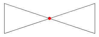
The blade should rotate around the center (the red dot), and the entire blade should be on the screen at all times.
Modify the Benham’s disk program from the notes so that the value of dA is printed near the upper-left corner of the screen.
Write a program that displays a PImage in the center of the screen and then rotates counter-clockwise as the mouse moves to the left, and clockwise as it moves to the right.
Modify the clock program in the notes so that the second hand slides smoothly around the clock instead of jumping from second to second.
Add another planet, with its own moon, to the solar system program from the notes. Make its speed and size different than the planet/moon already there.