Available Wednesday, May 23, 2001
Due Wednesday, June 6, 2001
Due by 12:00 noon on Wednesday, June 6, in the CMPT-150-ARC drop boxes outside K9507. Make sure you put your assignment in the box labeled for CMPT-150-ARC.
Question 1.(2 marks) Answer problem 2-8(b) from the text.
Original expression: F=ABC+~A~C+~A~B
to convert to AND and complement, we use demorgan to convert OR operations
(X+Y+Z) to AND ( ~(~X~Y~Z) ):
F=~(~(ABC)~(~A~C)~(~A~B)
Question 2.(6 marks) Answer problem 2-14(a) and (c) from the text.
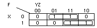
(a)
F=XY+~XZ
(c)
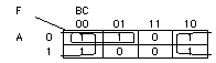
F=~A~B+~C
Question 3.(8 marks) Answer problem 2-16(b) and (c) from the text.
(b)
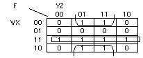
F=WX+~XZ
(c)
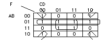
F=~AB+~B~D+BD
Question 4.(8 marks) Answer problem 2-32(b) from the text.
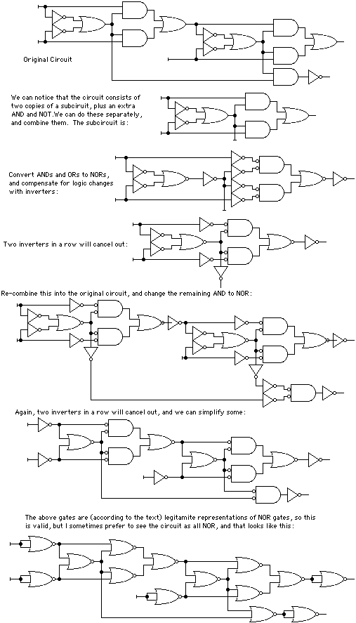
Question 5.(16 marks) A parity generator is a circuit which will prepare
a word of bits to be sent and received using parity error correction. The
circuit takes a word of data as input, and produces a parity bit as output.
The word of data and the parity bit are transmitted together.
A parity decoder is a circuit which receives a parity-encoded transmission,
and uses the parity bit to check the transmitted word for errors.
SOLUTION
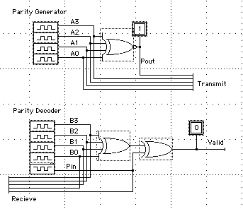
Parity Generator:
The parity generator has 4 inputs and 1 output. We want the combined 5
bits to have an odd number of 1s. This means that if the 4-bit input word
has an even number of 1s, the parity bit should be 1, and if the 4-bit input
word has an odd number of 1a, the parity bit should be 0. This implies that
the parity bit is the even function. We know that XOR is the odd function, so
XNOR is the even function. a 4-bit XNOR will provide the functionality we need.
Parity Decoder:
The parity decoder has 5 inputs and 1 output. The output will tell us if the transmission
was valid or not. We must decide how to interpret the output. I will decide that
output=1 indicates a successful transmission (odd number of 1s) and output=0 indicates
a non-successful transmission (Even number of 1s). The circuit therefore should be
a 5-bit XOR (which is the odd function). DesignWorks does not have a 5-bit XOR, so
we take a 4-bit XOR and a 2 bit XOR and combine them to create a 5-bit XOR. We can
do this because in class we learned that
The circuits:
And the timing diagrams:
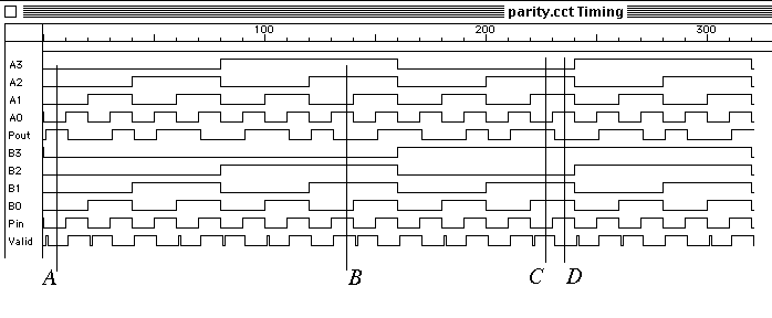
The first 5 lines of the timing diagram show the exhaustive test for the parity generator. We can see that there are always an odd number of "1"s between those 5 signals. In particular, at A there is one "1". The input word was "0000" and the parity bit provided the "1" to bring the count to one. At B, the input word was "1101" which already has an odd number of "1"s, so the parity bit was set to "0".
The last 6 lines of the timing diagram show the exhaustive test for the parity decoder. The following test cases are noted: